- 您现在的位置:买卖IC网 > Sheet目录3875 > PIC18F44J10T-I/ML (Microchip Technology)IC PIC MCU FLASH 8KX16 44QFN
PIC16F8X
1998 Microchip Technology Inc.
DS30430C-page 39
FIGURE 8-2:
CONFIGURATION WORD - PIC16F83 AND PIC16F84
8.2
Oscillator Configurations
8.2.1
OSCILLATOR TYPES
The PIC16F8X can be operated in four different
oscillator
modes.
The
user
can
program
two
configuration bits (FOSC1 and FOSC0) to select one of
these four modes:
LP
Low Power Crystal
XT
Crystal/Resonator
HS
High Speed Crystal/Resonator
RC
Resistor/Capacitor
8.2.2
CRYSTAL OSCILLATOR / CERAMIC
RESONATORS
In XT, LP or HS modes a crystal or ceramic resonator
is connected to the OSC1/CLKIN and OSC2/CLKOUT
pins to establish oscillation (Figure 8-3).
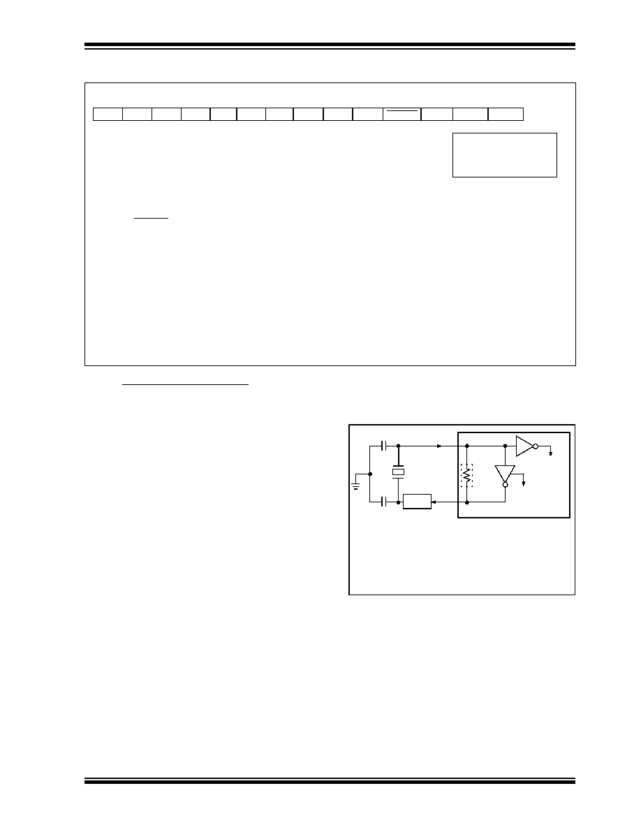
FIGURE 8-3:
CRYSTAL/CERAMIC
RESONATOR OPERATION
(HS, XT OR LP OSC
CONFIGURATION)
The PIC16F8X oscillator design requires the use of a
parallel cut crystal. Use of a series cut crystal may give
a
frequency
out
of
the
crystal
manufacturers
specifications. When in XT, LP or HS modes, the device
can have an external clock source to drive the
OSC1/CLKIN pin (Figure 8-4).
R/P-u
R/P-u R/P-u R/P-u R/P-u R/P-u
R/P-u
CP
PWRTE WDTE FOSC1 FOSC0
bit13
bit0
R
= Readable bit
P
= Programmable bit
- n = Value at POR reset
u = unchanged
bit 13:4 CP: Code Protection bit
1 = Code protection off
0 = All memory is code protected
bit 3
PWRTE: Power-up Timer Enable bit
1 = Power-up timer is disabled
0 = Power-up timer is enabled
bit 2
WDTE: Watchdog Timer Enable bit
1 = WDT enabled
0 = WDT disabled
bit 1:0
FOSC1:FOSC0: Oscillator Selection bits
11
= RC oscillator
10
= HS oscillator
01
= XT oscillator
00
= LP oscillator
Note1:
See Table 8-1 for recommended values of
C1 and C2.
2:
A series resistor (RS) may be required for
AT strip cut crystals.
3:
RF varies with the crystal chosen.
C1(1)
C2(1)
XTAL
OSC2
OSC1
RF(3)
SLEEP
To
logic
PIC16FXX
RS(2)
internal
发布紧急采购,3分钟左右您将得到回复。
相关PDF资料
PIC18LF24J10T-I/ML
IC PIC MCU FLASH 8KX16 28QFN
DSPIC30F6011T-20E/PF
IC DSPIC MCU/DSP 132K 64TQFP
DSPIC30F6010T-20E/PF
IC PSPIC MCU/DSP 144K 80TQFP
DSPIC30F4013T-20I/PT
IC DSPIC MCU/DSP 48K 44TQFP
DSPIC30F4013T-20I/ML
IC DSPIC MCU/DSP 48K 44QFN
DSPIC30F4012T-20I/SO
IC DSPIC MCU/DSP 48K 28SOIC
DSPIC30F4012T-20I/ML
IC DSPIC MCU/DSP 48K 44QFN
PIC24F16KL402-I/SO
IC MCU 16BIT 16KB FLASH 28-SOIC
相关代理商/技术参数
PIC18F44J10T-I/PT
功能描述:8位微控制器 -MCU 16 KB FL 1024 RAM RoHS:否 制造商:Silicon Labs 核心:8051 处理器系列:C8051F39x 数据总线宽度:8 bit 最大时钟频率:50 MHz 程序存储器大小:16 KB 数据 RAM 大小:1 KB 片上 ADC:Yes 工作电源电压:1.8 V to 3.6 V 工作温度范围:- 40 C to + 105 C 封装 / 箱体:QFN-20 安装风格:SMD/SMT
PIC18F44J11-I/ML
功能描述:8位微控制器 -MCU 16KB Flash 4KBRAM 12MIPS nanoWatt RoHS:否 制造商:Silicon Labs 核心:8051 处理器系列:C8051F39x 数据总线宽度:8 bit 最大时钟频率:50 MHz 程序存储器大小:16 KB 数据 RAM 大小:1 KB 片上 ADC:Yes 工作电源电压:1.8 V to 3.6 V 工作温度范围:- 40 C to + 105 C 封装 / 箱体:QFN-20 安装风格:SMD/SMT
PIC18F44J11-I/PT
功能描述:8位微控制器 -MCU 16KB Flash 4KBRAM 12MIPS nanoWatt RoHS:否 制造商:Silicon Labs 核心:8051 处理器系列:C8051F39x 数据总线宽度:8 bit 最大时钟频率:50 MHz 程序存储器大小:16 KB 数据 RAM 大小:1 KB 片上 ADC:Yes 工作电源电压:1.8 V to 3.6 V 工作温度范围:- 40 C to + 105 C 封装 / 箱体:QFN-20 安装风格:SMD/SMT
PIC18F44J11T-I/ML
功能描述:8位微控制器 -MCU 16KB Flash 4KBRAM 12MIPS nanoWatt RoHS:否 制造商:Silicon Labs 核心:8051 处理器系列:C8051F39x 数据总线宽度:8 bit 最大时钟频率:50 MHz 程序存储器大小:16 KB 数据 RAM 大小:1 KB 片上 ADC:Yes 工作电源电压:1.8 V to 3.6 V 工作温度范围:- 40 C to + 105 C 封装 / 箱体:QFN-20 安装风格:SMD/SMT
PIC18F44J11T-I/PT
功能描述:8位微控制器 -MCU 16KB Flash 4KBRAM 12MIPS nanoWatt RoHS:否 制造商:Silicon Labs 核心:8051 处理器系列:C8051F39x 数据总线宽度:8 bit 最大时钟频率:50 MHz 程序存储器大小:16 KB 数据 RAM 大小:1 KB 片上 ADC:Yes 工作电源电压:1.8 V to 3.6 V 工作温度范围:- 40 C to + 105 C 封装 / 箱体:QFN-20 安装风格:SMD/SMT
PIC18F44J50-I/ML
功能描述:8位微控制器 -MCU Full Spd USB 16KB 4KBRAM nanoWatt RoHS:否 制造商:Silicon Labs 核心:8051 处理器系列:C8051F39x 数据总线宽度:8 bit 最大时钟频率:50 MHz 程序存储器大小:16 KB 数据 RAM 大小:1 KB 片上 ADC:Yes 工作电源电压:1.8 V to 3.6 V 工作温度范围:- 40 C to + 105 C 封装 / 箱体:QFN-20 安装风格:SMD/SMT
PIC18F44J50-I/PT
功能描述:8位微控制器 -MCU Full Spd USB 16KB 4KBRAM nanoWatt
RoHS:否 制造商:Silicon Labs 核心:8051 处理器系列:C8051F39x 数据总线宽度:8 bit 最大时钟频率:50 MHz 程序存储器大小:16 KB 数据 RAM 大小:1 KB 片上 ADC:Yes 工作电源电压:1.8 V to 3.6 V 工作温度范围:- 40 C to + 105 C 封装 / 箱体:QFN-20 安装风格:SMD/SMT
PIC18F44J50T-I/ML
功能描述:8位微控制器 -MCU Full Spd USB 16KB 4KBRAM nanoWatt RoHS:否 制造商:Silicon Labs 核心:8051 处理器系列:C8051F39x 数据总线宽度:8 bit 最大时钟频率:50 MHz 程序存储器大小:16 KB 数据 RAM 大小:1 KB 片上 ADC:Yes 工作电源电压:1.8 V to 3.6 V 工作温度范围:- 40 C to + 105 C 封装 / 箱体:QFN-20 安装风格:SMD/SMT